Heat exchangers have a wide range of applications. These applications include refrigeration systems, condensers, metal smelting industries, power plants, etc. Heat exchangers are devices that are used to transfer heat from a high-temperature stream to a lower-temperature stream.The heat transfer process in any heat exchanger is carried out in three ways, depending on the temperature of the fluid: conduction, convection, and radiation.
Heat exchangers are categorized by various aspects. The most common types of heat exchangers include shell and tube heat exchangers, plate heat exchangers, spiral or coiled plate heat exchangers, and air-cooled heat exchangers. Although small and seemingly insignificant, heat exchangers are of great importance in making the production process profitable and economical. The amount of energy consumed, which is supplied by fuel and constitutes a large part of the costs of a building or factory, is directly dependent on the efficiency and performance of the heating system.
Plate heat exchanger:
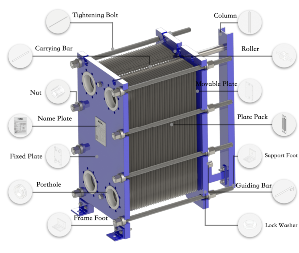
A plate heat exchanger consists of a number of pressed plates of various shapes that are placed between two fixed and movable steel plates (frames) and are aligned by two upper and lower rails.
The set of plates located between the fixed and movable frames are pressed together by a number of screws. Between each two plates there is a special gasket that acts as a seal between the two plates and creates a channel for the flow of fluids. The set of plates (plate pack) while pressed together creates 4 channels for the entry and exit of hot and cold fluids. These fluids move alternately in the channels formed by the plates, and heat transfer occurs with high efficiency.
- Gasketed plate heat exchangers
A gasketed plate heat exchanger is a highly efficient and high-efficiency heat exchange device that is composed of a number of thin corrugated steel metal plates and gaskets. A gasket of suitable material (depending on the fluid and temperature) is placed between each plate to seal and create a passage channel for the fluids, so that the hot and cold fluids flow independently in the flow channels on both sides of each plate. The heat transfer coefficient of the GPHE is 3 to 5 times higher than that of the shell and tube heat exchanger, Because hot and cold fluids can reach a high degree of turbulence when flowing through plate channels that have a specific wavy shape on the surface of the plate.
- How does a gasketed plate heat exchanger work?
In a gasketed plate heat exchanger, for each plate, usually made of steel, there is an elastomeric gasket that is placed in the grooves in the plates and is responsible for sealing the flow channels. By placing the appropriate number of gaskets and plates on top of each other, channels for the fluid to pass through are created.Cold and hot fluids enter the exchanger from two separate inlets, and temperature exchange occurs through contact of the cold and hot fluids with the back and top of the plates.
The plates are assembled between two steel frames with appropriate pressure and by tightening bolts. The channel plates and frames are suspended from an upper carrier bar and restrained by a lower guide bar. The physical design of the gasketed plate heat exchanger is such that it is easy to clean the exchanger and change its thermal capacity by adding or removing plates.
Advantages compared to shell and tube exchangers
- High heat exchange efficiency and low operating cost, compared to shell and tube heat exchanger and 3-5 times higher heat exchange capacity.
- Compact design, small footprint, easy installation, and occupies 1.5 to 1.8 times the size of a shell and tube heat exchanger.
- Convenient maintenance, easy to disassemble and clean.
- Easy capacity change, by opening the converter and increasing or decreasing the plates.
- The NTU value is large and the minimum temperature difference can be 1 degree.
-
- Shell and tube exchangers
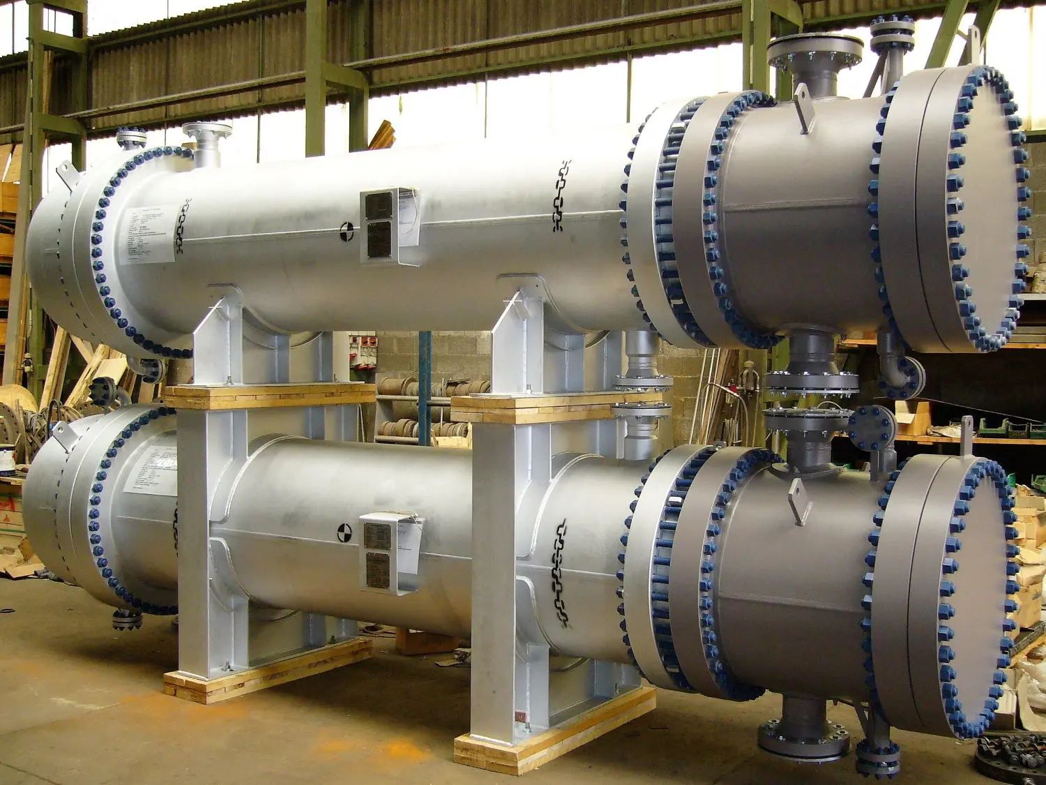
The shell and tube heat exchanger is the most widely used type of exchanger in the industry and is the most suitable type of exchanger for high pressure and high temperature applications. Shell and tube heat exchangers consist of a bundle of tubes or pipes embedded in a cylindrical shell, also called a shell and tube heat exchanger. One fluid flows through the tubes and one fluid flows around the tubes (inside the shell), and due to the temperature difference between the two, heat is transferred from one fluid to the other through the walls of the tubes.
- How does a shell and tube heat exchanger work?
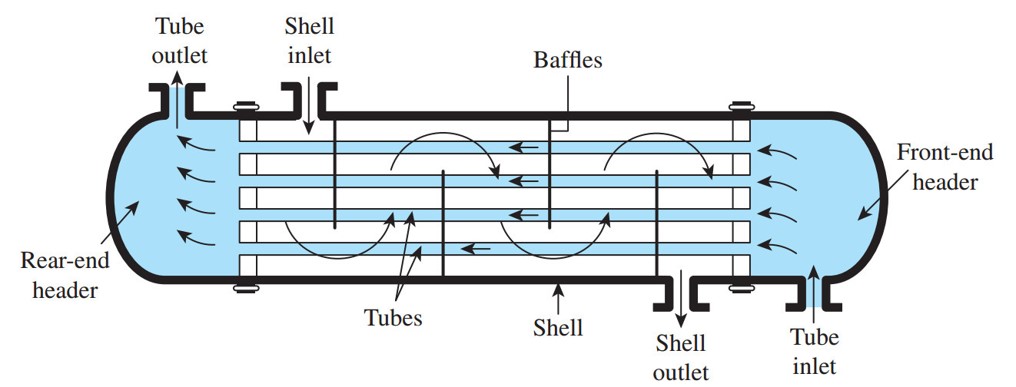
The basic idea of shell and tube heat exchangers is to pass a hot fluid through a cold fluid, without mixing the two, so that only their heat is transferred. The diagram above shows two inlets and two outlets, where each of the two fluids enters through its respective inlet and exits through its respective outlet. The tube side flow passes through the tube bundle (which is protected by metal plates known as tubesheets/tubeplates) and exits the tube outlet. Similarly, the flow on the shell side starts at the shell inlet, passes through the tubes, and exits at the shell outlet. The doors on both sides of the tube bundle create reservoirs for the flow to the tube side and can be divided into several sections depending on the specific types of heat exchangers.
Each tube contains a turbulator that creates turbulent flow in the tubes, preventing fouling and also increasing the heat transfer capacity of the exchanger. Designers also use obstacles called “baffles” to create turbulence in the shell, which maximizes the amount of heat exchange between the shell-side fluid and the cooling tubes. The shell-side fluid must move around these baffles, which causes the flow to pass over the tube bundle many times, thus transferring energy and exiting the heat exchanger at a lower temperature.
- Advantages of shell and tube heat exchanger
1. Ability to withstand the highest temperatures and fluid pressures due to its robust structure
2. Maximizing heat transfer surface area in a limited space by using a stack of closely spaced tubes next to each other
3. Lower initial price (compared to air-cooled, plate, etc.)
4. Ability to descaling in short and long term periods physically and chemically (designed to be easily assembled and disassembled)
5. Ability to design and manufacture with special raw materials (such as steel) in specific applications where fluids are corrosive.
6. If a leak occurs in the tubes, the leak can be easily identified and repaired.